Phone-Controlled Robot Arm
My project is a Robot Arm that can move in all directions and grab objects with it’s claw. It uses the ESP32 to connect to a phone through bluetooth so the phone can control the Robot Arm.
| Engineer | School | Area of Interest | Grade |
|---|---|---|---|
| Siddharth Maddikayala | American Highschool | CS/AI | Incoming Freshman |

Demo Night
Overall, I am glad with how my project turned out. I got to finish it and also add a cool modification which was voice control.
Final Milestone

For my final milestone, I added voice control to my arm. Whenver I say the commands up, down, left, right, forward, or backward, then the robot will move in the following direction. I used the mit app inventor’s default speech recognizer to recognize each word. After I’ve identified a word, I need to send data to the arm telling it to move. I already have a function that sends data when the slider is moved, so all I had to do was change the corresponding slider’s position by +/- 10 depending on the word that was recognized by the speech recognizer.
Second Milestone
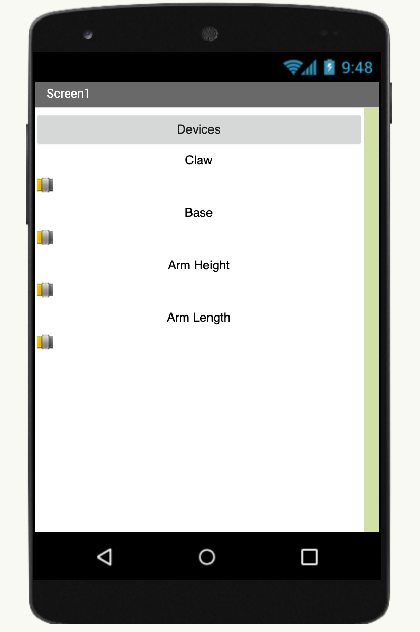
For my second milestone, I made a phone app and was able to control the robot arm with sliders on my phone. I did this by using bluetooth to communicate with the esp32. Everytime the slider’s value changes, then it sends that value to the esp32, and then I use the ‘Servo.write()’ function of move the servo. For bluetooth, I used the mit app inventor’s standard Bluetooth Client to connect to the ESP32. I use the method AdressesandNames to display a list of all the devices. When the esp32 is selected, I connect to it and then I can control it.
First Milestone
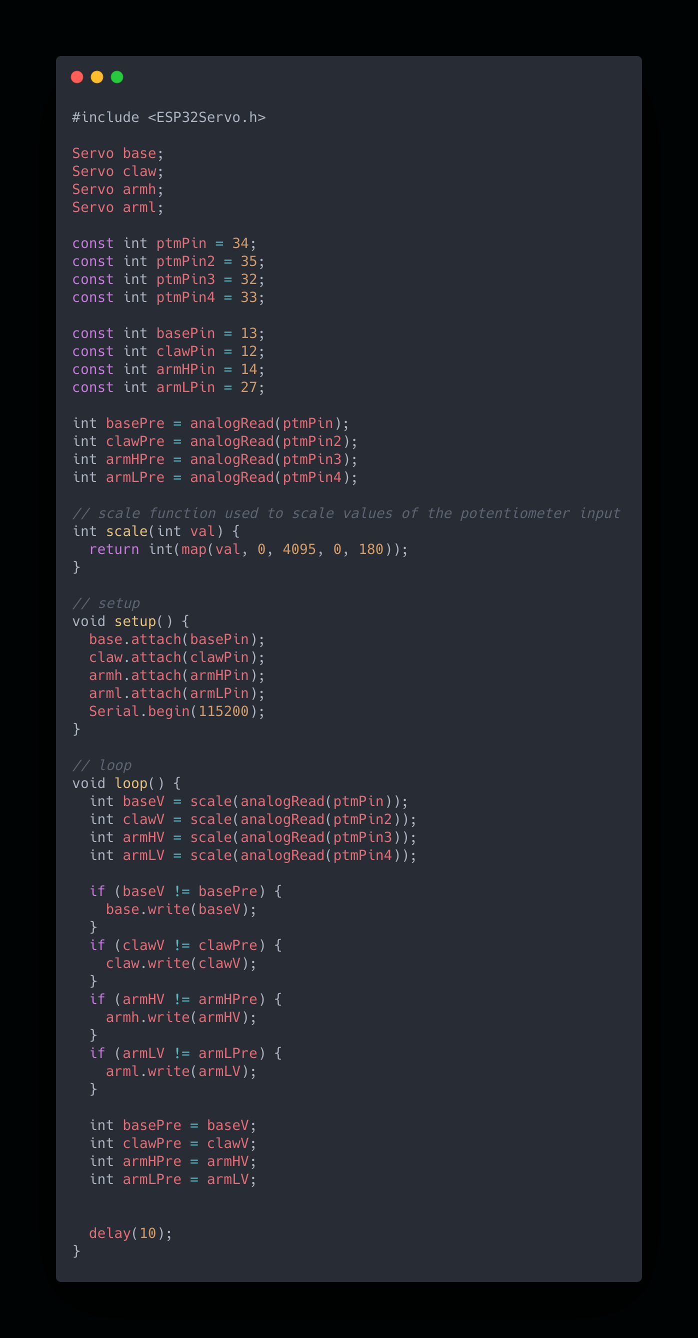
My first milestone was that I finished building the robot arm, and also got the servo motors working and using the potentiometers to move the motors. I connected each potentiometer to an analog pin so I could get an input for the motor. Servo values range from 0 to 180, but potentiometers range from 0 to 1023 so I needed to use the map function to scale down the input. Then I used the Servo.write() function to send the value to the servo and move it.

Wiring:
- Red wires: power
- Black wires: ground
- Green wires: GPIO pins
This is my curcuit. I had a total of 4 motors and potentiometers. Both had a similar design for their curcuits: a pin for power, a pin for ground, and a GPIO pin. The 5 volt pin on the arduino can’t support 4 or more motors and I needed more power so I used a battery holder of 4 for 6.5V to power the servos. The potentiometers had a 3.3V power source.